Atopile is another thing in the circuits-as-code space: https://github.com/atopile/atopile
As a half EE/half SWE I think there are significant benefits to circuits as code but I'm not impressed with this one. Atopile has a narrower focus (autorouters are really really hard) and doesn't use as many buzzwords. Like why on earth does a "web first approach" matter at all for hardware development?
But also, GUI tools are getting better, Kicad 9 had a lot of changes that made templating / reusing blocks easier. And it works fine if not great with version control.
I don't see circuit-as-code taking off with humans anytime soon, it's much better but not enough better to convince EEs many of which don't code much or at all. But I can see it becoming much more common as LLMs get better at complex circuits.
It's probably a simple economics thing. You can hire out a contract PCB design for a reasonable cost and the long poll is getting back physical prototypes. Contrast to HDLs displacing schematic based designs for ASICs and programmable logic, where simulation allows for rapid development.
> I don't see circuit-as-code taking off with humans anytime soon
I don't agree with this. Circuits aren't really anything more complex than anything else humanity has had to figure out. Most knowledge in this area seems solvable.
Maxwell's equations have been known for a century.
For whatever reason, Software Engineering and Hardware Engineering even though they rely upon the same fundamental physics, are so very different? And apparently can't be reconciled? No. I don't believe it.
PCB layout is as much art and black magic as it is science. I'm not sure why you dismiss the complexity so easily, this definitely is not just a matter of applying Maxwell's equations.
Layout is a puzzle, especially with particularly high density layouts, but some of this is ameliorated by high layer count and fine trace/space boards becoming cheaper. Definitely not black magic. RF layout is black magic, let's not steal their thunder here.
High speed PCBs are RF. At high enough frequencies, traces become waveguides, and the result cannot be predicted analytically. Simulation is your only light in this mess.
> For whatever reason, Software Engineering and Hardware Engineering even though they rely upon the same fundamental physics
Software engineering isn't a thing besides being an ego title.
Software is "ship now, patch later"
Hardware is engineered, it must be correctly designed from the beginning and cannot be easily modified in the field
I don't know why anyone wants to shove big heavy applications into browsers. Are they imagining you'd use your phone for this?
Are we not teaching kids how to publish desktop applications these days or what?
It's just not that we are imagining that people will be using phone to build PCB's, we also have a cli which perform better than the browser playground!
My guess is the cross platform story.
For cross platform development we barely have any decent, free development tools. It's a lot easier to find JavaScript developers in most places than c++/c# developers.
Wish I could comment on the routing like others but the render is stuck at 96.2% for me. Nothing else on the page shows it on my phone so I assume that's the problem. (And of course nothing in the log of error tabs).
I think just looking at the first code example you can already see the problem. A lot of duplication and hand written or auto generated code. I thought the point was to define it in the code. Put an array of pin functions. For loop the footprint. That kinda thing. This looks like a mess to get started with and even worse is at higher point count parts it looks like it'll balloon in maintainability. Altium has very solid footprint generators with a nice menu. This looks like it's missing an overarching API for creating these long lists of parameters. Doesn't feel like the juice is worth the squeeze on this one. If it's a simple schematic, just do it by hand. If it's complicated, this feels harder to wrangle.
Another example of weird code is the previousLedName. Like like really that variable isn't used and the first term of the && should be that indeed check. But even more so, it should be an if statement not rely on remembering short circuiting (lazy evaluation) tricks. Because that's what you mean. You mean if it's not the first one, connect to the previous one. So, the code should say that. I find it hard to believe such a high level language would prevent it.
I think the pin label lists don't make sense. They're maps where the value is an array where the first element is the key? Why is this not just a list of pin numbers to names or a map of they're not contiguous whole numbers?
And then the icing on the cake: you still have to define where in XY everything is.
So really, in thinking about this, this looks more like a file format than a tool. And maybe that's fine. But I'll stick to the native formats of the tools.
A lot of deserved criticism in the comments here tonight, but more generally, I have to ask - what's the deal with all these code/text to CAD/PCB things?
There's a half dozen of them in any category, they are all different, they all seem to struggle badly with anything outside of simple examples, none of them appear to consider how things fit together in the real world, you almost never see any of them used for anything more complicated than a keyboard layout or an LED matrix, they all have reinvented the wheel instead of using industry standard formats, and they all talk about the "difficulty of using traditional tools" as though placing each XY point in space in your head is easier than dragging things around the screen like in MS Paint. You also never see any serious hardware people use them. Every one wants to do it all from keyboard to finished product instead of being satisfied as a intermediate tool that does one thing well.
But, they all have very polished documentation, they come with examples, they have nice looking websites, and it's obvious someone put a decent amount of thought into making them. It's not like they are useless either. Making a big grid of things? It's nice to be able to write an algorithm to do that instead of entering them by hand.
I brought this up in that post about the LLM to CAD thing the other day. It's like people keep saying "hardware is hard" but then keep trying to solve it like they would work on software problems.
At a high level I think a lot of it is simply hubris from software engineers who see the basics of electrical engineering or 3D CAD and think that the basics are all there is to the field. It's the same as when people see a hello world or fizzbuzz program and think that's representative of software engineering before proposing no-code solutions.
Anecdotally as someone who studied mechatronics: Software engineers are far worse than any other engineering field in assuming that everything is trivial compared to SE.
When I'm using Fusion 360, I can't stop thinking that this whole experience would be much better with code. It has awesome underlying engine, but GUI UX is just terrible. I'd prefer to describe objects in code, observing code output in real-time on adjacent panel, using proper text editor to apply changes.
I've used OpenSCAD, it's not the thing I want, it doesn't have constraint solving, the key is using constraint solving with feedback to highlight warnings, etc.
Now maybe I'm not talking about complete replacement of GUI with code, but rather an alternative view, where you can either use GUI to model objects, or switch to code where everything is synchronized.
They're aiming to recapitulate the success of HDL design in the IC world. The jitx folks are pretty clear about that. There are a lot of problems with that that could be a medium-sized think piece, but some things folks are doing in the space are neat. PCB-level EDA is overdue for better design checks, for example.
I think the most recent surge is due to LLMs, the only way to (easily) apply them is to have some form of code like textual representation of your problem domain so "circuits as code" is the obvious way to wedge them into electronic engineering.
Kicad also makes it easier to make such startups as it has an open file format with several different free viewer tools and lots of content (schematics/footprints). If that ecosystem didn't exist I don't think you would see as many of these startups around, but with that you can launch one of these tools within a initial VC funding
XY coordinates are more or less temporary. We are working on llm-compatible layout definitions which operate more with constraints or loose auto placement specifications than XY directly eg https://docs.tscircuit.com/footprints/constraint
I can only talk about my own experience trying to learn FreeCAD for a project[1] I eventually used Build123d for.
For me FreeCAD was highly unintuitive. Everything is a chain of operations/modifications on solids(good!) but for some reason it won't let you modify anything but the last element in the chain?
I was working on a trackball device so part of the parameters are the size of the trackball you'd use.. This affects pretty much all the parts in the chain but you have to decide all the way in the beginning on what size you need. In code-based systems this is simply a variable you define in the beginning and can modify at any point. Let's say I want to use M2 screws instead of M3 ones or use a larger bearing: I can just change a variable at the start of the script.
Being an absolute beginner I also had to reorganize stuff a couple of times. With python/build123d that's a matter of shuffling around code in your editor. I don't even know how you would do that in FreeCAD without deleting and redoing large swathes of your design.
Then there's my general unease dealing with this opaque representation of your model where any previous step you may have took puts your project into some state that can't really be undone or at least not intuitively found. When working with code and something breaks you can usually recover from a broken state by stripping out whatever you were working on. At worst you can just go back to your last revision in Git. With GUI-based tools you have to pray that Undo/Redo gets you to a state you wanted without losing too much.
Maybe the proprietary tools work better here but they don't run on Linux and I also don't use them for ethical reasons.
Admittedly the whole experience with build123d is anything but perfect. I _would_ like to just pick stuff with the mouse where possible and have a nice real-time display of changes I make. Ideally I'd like to see some sort of editing graph where you can see intermediate steps and pick visually parts to operate on for the next step - all underpinned by a concise textual representation that can be versioned.
Maybe this is me showing SE hubris but it's how I was able to get a reasonably complex personal project done. Maybe programming somehow broke my brain, IDK.
The only thing FreeCAD has going for it is that it's free, everything else about it is far behind the serious commercial tools.
> Ideally I'd like to see some sort of editing graph where you can see intermediate steps and pick visually parts to operate on for the next step - all underpinned by a concise textual representation that can be versioned.
This is exactly how most[1] commercial 3D CAD packages have worked for at least the last 30 years, they've done it longer than Git or SVN have existed. Specifically everything is represented as a list of operations (sketches, extrusions, chamfers, etc.) and you can freely go back and edit any step, or you can click on any part of a model and see exactly what step was used to generate it.
Some CAD packages will let you see a textual representation, but it's only really useful for scripting when they do. The versioning tools that are built in to any CAD package are far better than trying to work with text.
[1]: Excluding the more obscure CAD packages like Creo that do things differently to fit in to a specific niche.
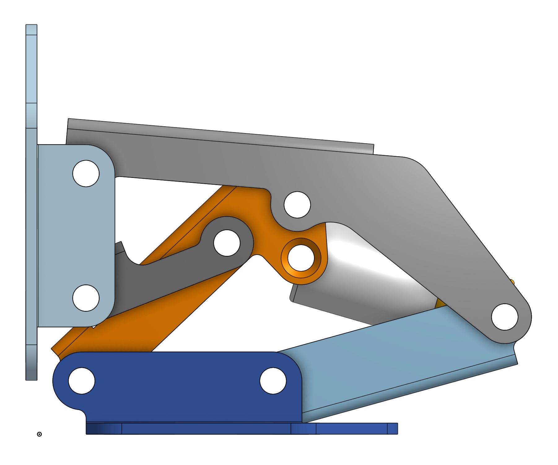
As an example of this:
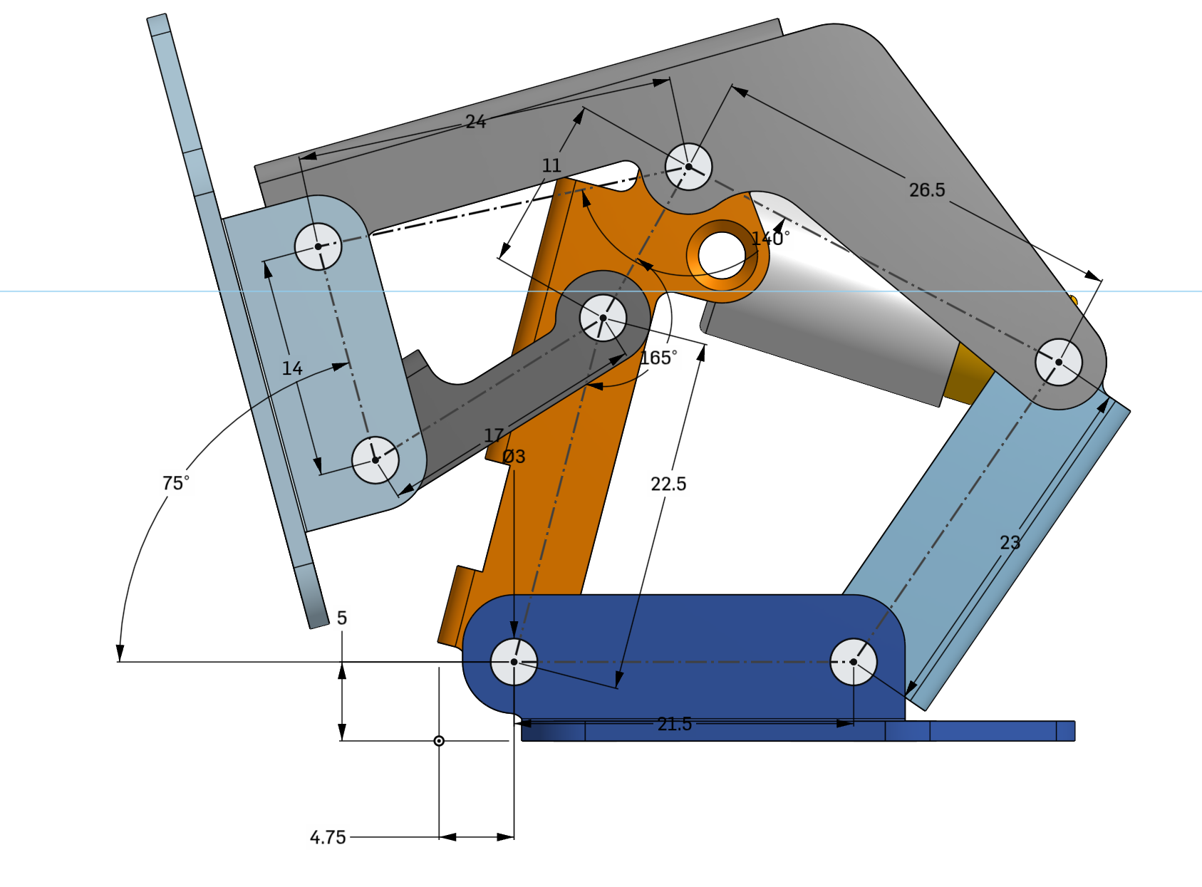
Here's a hinge mechanism: https://files.catbox.moe/06g9cg.png
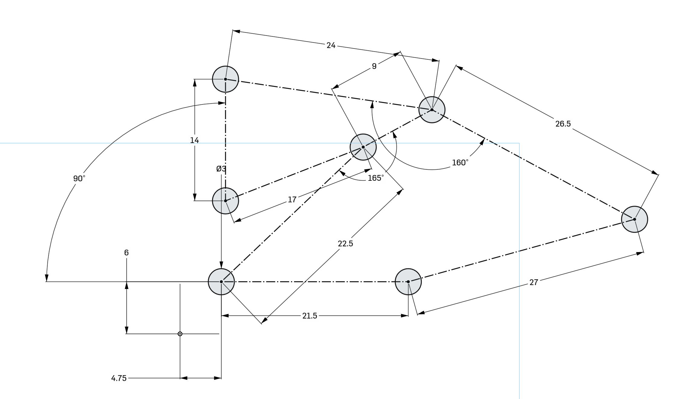
Here's the very first sketch in the timeline, I've just clicked on this to edit it, there was no undoing required: https://files.catbox.moe/xzr3un.png
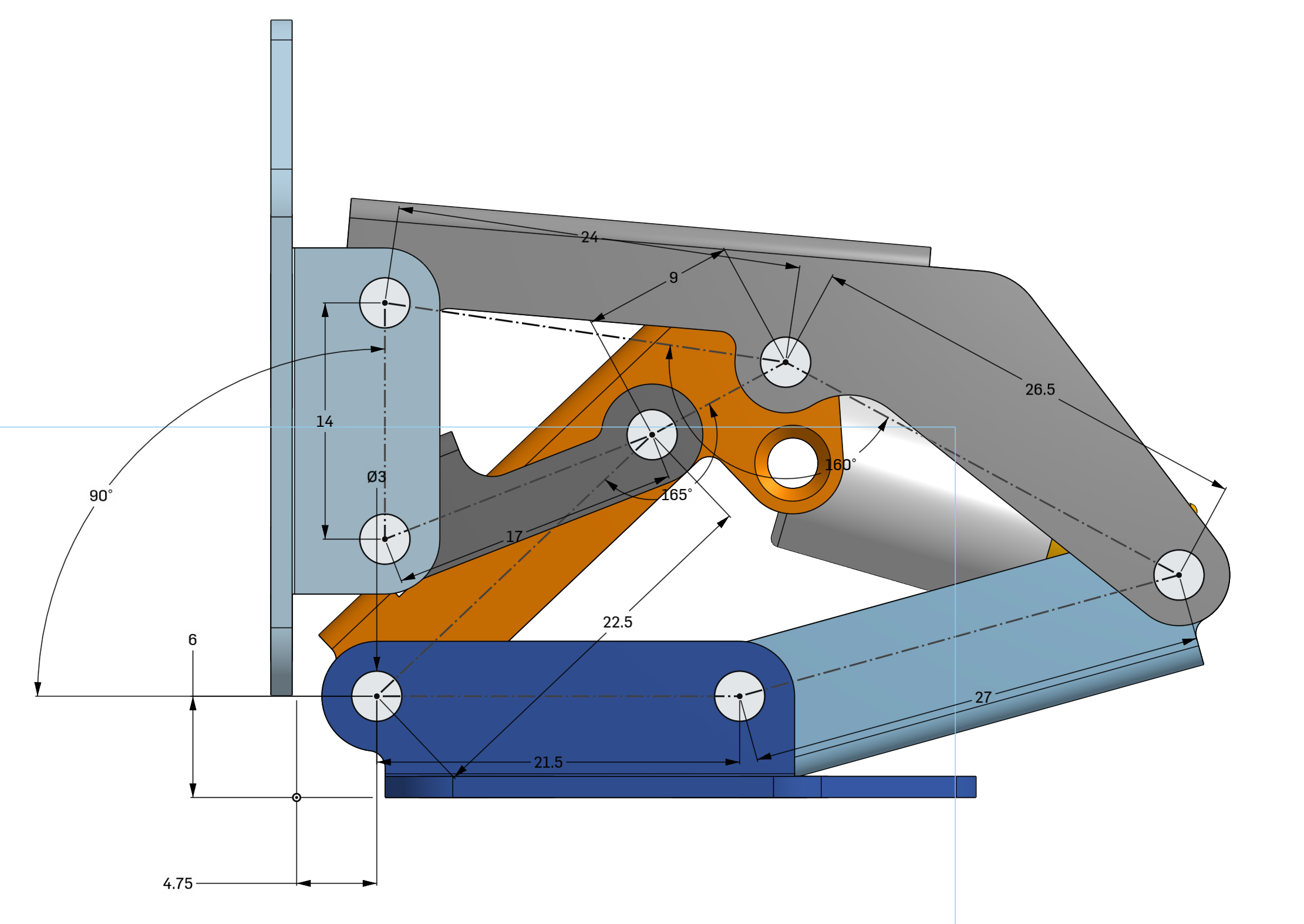
Here it is overlaid on the model, which just requires a single mouse click to toggle: https://files.catbox.moe/339fvg.png
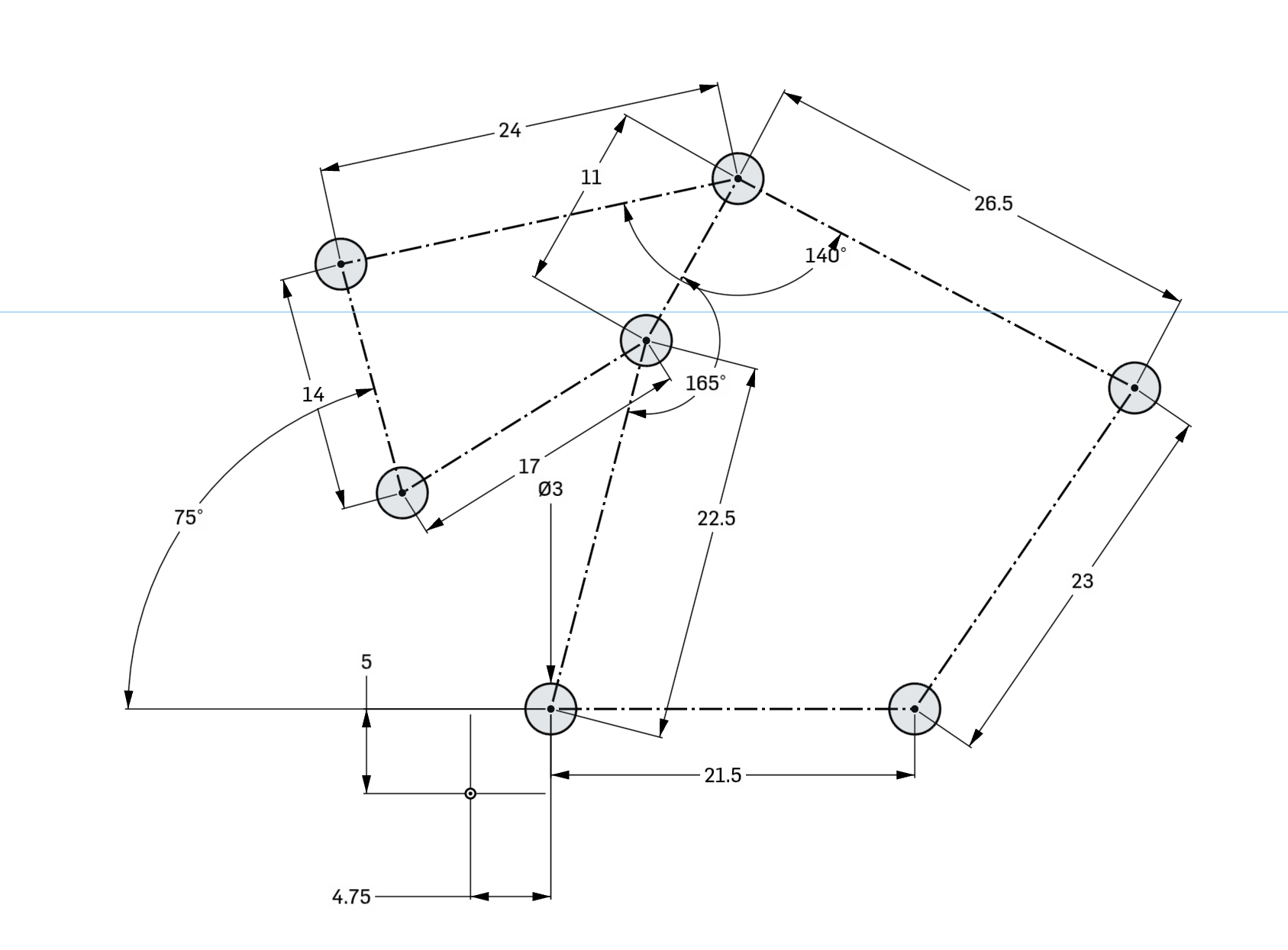
Here it is after I changed a bunch of numbers: https://files.catbox.moe/pvykrx.png
Here's what it looks like when I press the button to show the final model again: https://files.catbox.moe/6bjc0c.png
Just like that the entire model has changed based on the initial sketch. I didn't have to go edit any other features here.
As a bonus here's the assembly being moved by dragging the mouse after those changes, showing that this might not be the most well-designed hinge after those changes: https://files.catbox.moe/eztkja.mp4
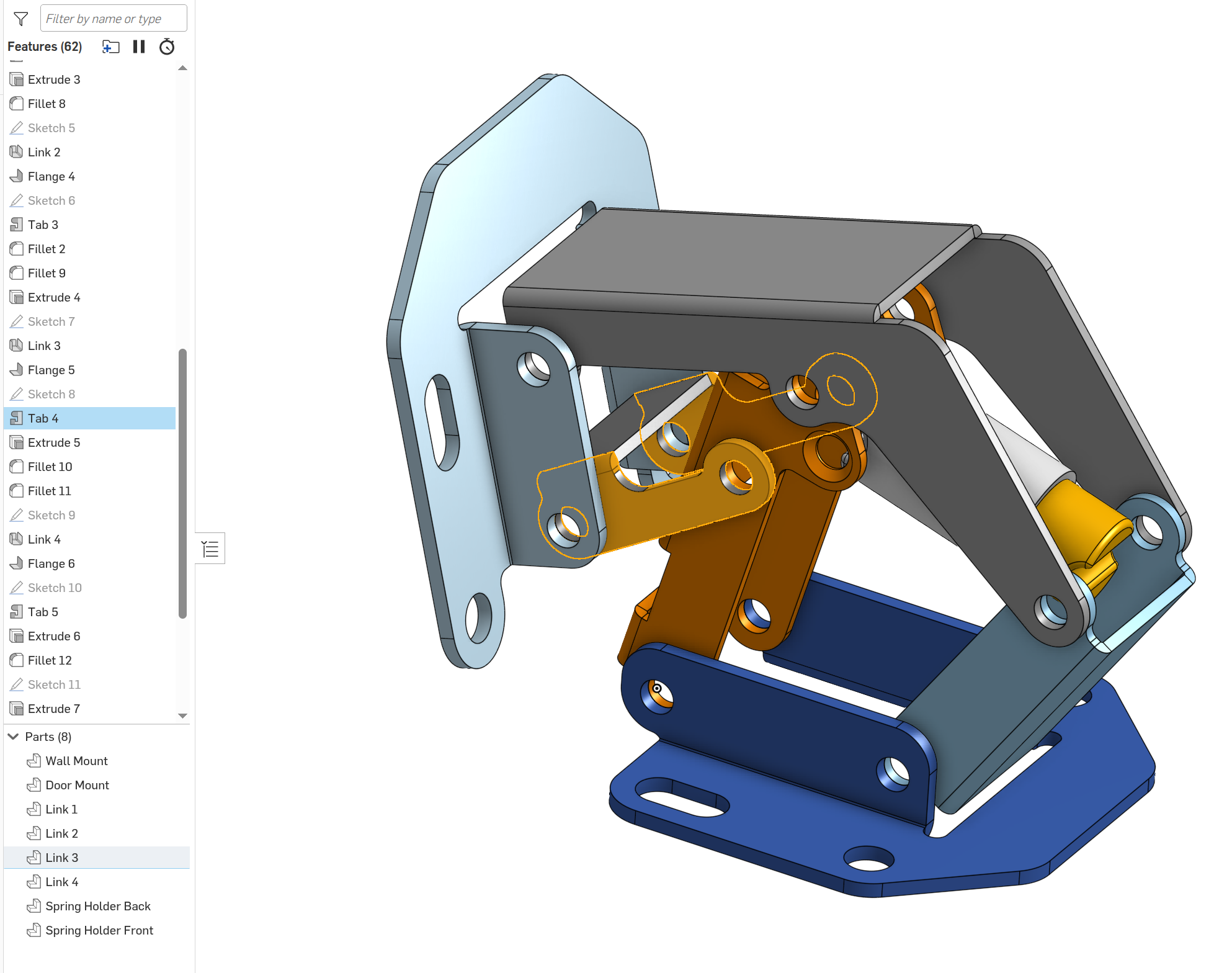
Also here's the timeline I mentioned, you can see how I've clicked on a feature and it shows me exactly what it did, this also works when clicking on part of the model: https://files.catbox.moe/f0bb2k.png
I'm genuinely surprised by how awful the resulting PCB is. A trivial LED matrix like this is pretty much the best-case scenario for tooling like this. Not being able to handle this is a pretty damning - although a decent bunch of the blame should probably be placed on whatever third-party autorouter they are calling out to.
Even with better results, the big issue with tools like these is that they simply don't match with the kind of development style that's needed for the problems at hand. You see the same issue with those drag-and-drop visual programming languages, or scripted modeling like OpenSCAD: they end up making fairly trivial details slightly easier, while significantly complicating the meat-and-potatoes. Nobody cares about a neat little part placement for-loop if it generates a living hell of autorouted spaghetti you can't possibly interpret and fix manually.
In reality the low-hanging fruit has already been covered by existing tooling. Automatically generating symbols and footprints from textual descriptions is routine practice, and software like KiCad already has a reasonably usable scripting API and a well-documented file format. A lack of code-based code-based EDA hasn't stopped projects like Ergogen[0] from popping up. The main limitation for additional automation is a lack of reliable input data, and user-side tooling can't fix that.
(tscircuit maintainer here) It might be easier to think of tscircuit as an electronics CAD kernel. We're MIT licensed and web-compatible, so we would make a great foundation for people building new EDA tools or people who would like to generate electronics (think domain-specific tools, e.g. a website that allows you to quickly build a custom keyboard)
FWIW In this case I think this board called out to freerouting for the routing. Companies have reached out to us with autorouting APIs, so we'll support different vendors and hopefully allow enough constraint-specification for people to get good results. Autorouting is important for reusability, even if it's routing between manually-routed sections (e.g. fanouts)
SVG PCB is a similiar concept. The nice thing is that it allows both code and gui manipulation of the design.
I built a WiFi-controlled RGB LED matrix using tscircuit, a library that lets you design PCBs with JavaScript instead of traditional CAD tools.
I took a stab at something like this. My intent was that you’d be sitting at a Common Lisp REPL, and start entering commands.
As you did this, a graphical window would show your components and traces. I considered similar to a legacy AutoCAD, way back before pointing devices were commonplace.
I had a whole simple dialect to easily identify traces, which you would continuously split with points, then nudge them around or anchor next to other points.
I honestly felt, especially for the small board project I was working on that writing this from scratch would have been faster than fighting KiCAD or any of the similar tools.
But I was stymied with finding a good way to get graphics out of CL on my Mac. I even considered doing it all in SVG with some kind of auto reloading file, and just rewriting it each time.
Obviously I did not put a lot of effort into it, had enough friction to move on to something else.
Interesting, reminds me of a project my colleague has just been working on: using KiCad + python to auto-place LEDs at specific coordinates on a PCB. Instead of positioning them as a regular matrix, the LED locations are derived from the shape of a racing circuit: https://ledsrace.at/zandvoort (routing and non-LED part of the layout was still done manually)
I don't think 100% auto-placement/routing will be able to take over manual layout, but there is definitely lots of potential for further automation!
This is a really good use case, though I'd be surprised if there aren't macros to do simple grid layout already in Altium or KiCad. It's the sort of thing you'd find in a badly documented Eagle userscript. I recently made a smaller PCB with 30 LEDs in a specific colour arrangement and even that was a pain by hand.
I guess it kind of works, but why would you? I find it quite therapeutic designing PCCB's. My last try at getting AI to draw a circuit diagram was actually quite hilarious: https://rodyne.com/?attachment_id=1753
i scaned the article but didn't see this. declarative netlist is probably ultimately the right thing. but one place where I got alot of leverage was writing generators for footprints. its so much nicer to say 'this pad is 0.8 x 0.3" and i'd like two rows of them separated by 4mm with a 1mm pitch than to draw little rectangles with the mouse and getting them all to line up. i dont know if more professional tools do this, but integrating that into kicad made me much happier about the whole process.
Honestly? I want a footprint editor with constraint-based modeling.
The datasheets often show measurements like the horizontal distance between the leftmost side of the left-row pads and the rightmost side of the right-most pad, and the distance between the rightmost side of the left-row pads and the leftmost side of the right-row pads.
Converting that into the stuff you need to enter in the editor (width of pad, distance between center of pad and center of footprint) isn't hard, but it is cumbersome and error-prone. Being able to directly enter it as constraints[0] would make it literally an order of magnitude easier to input, and it would allow for a simple 1:1 comparison with the datasheet for verification.
[0]: Something like https://wiki.freecad.org/images/thumb/7/71/FC_ConstrainedSke...
tscircuit maintainer here, we actually do support constraint-based modeling for footprints, although we don't use it often because we also support "short string" footprints which are often faster
What I'm missing is something like <pinheader>, just for generic connectors - say, <connector variant="[microusb,miniusb,usba-female,usba-male,vga-male,vga-female]">.
Also, for resistors, is there a chance for PTCs and NTCs? And <diode> would benefit IMHO from a variant="[zener, schottky, photo]" plus associated parameters for them.
We think that intuitive element names should be added to the tscircuit spec, even if they're redundant/there are multiple ways to do something. Right now you would probably use a <chip /> (very general purpose), but <connector /> is a great proposal for an element.
Yes diodes should have variants, I was surprised this wasn't already in the spec and created an issue to add it: https://github.com/tscircuit/props/issues/211
Yes we would support PTCs and NTCs for resistors, in general anything that helps with simulation, part selection, design intent, functionality, placement or appearance is in scope.
> We think that intuitive element names should be added to the tscircuit spec, even if they're redundant/there are multiple ways to do something.
Definitely makes sense, the question IMHO is what is the best way to interface with existing parts libraries. Making up individual names for each of the probably hundreds of thousands of connector types is going to be a looot of work.
And then, to add insult to injury, for some connectors there are so many different sub-variants as well. RJ45 with and without magnetics (I see inductors and (auto)transformers aren't present at the moment either) and LEDs, USB-C with some connectors being flush with the PCB and others that are designed to be placed in a PCB cutout... or PCIe connectors which can be had in physically closed and cutout variants (aka, an x1 socket that accepts x4/8/16 cards).
I hate connectors, in case it isn't apparent :'D
> Yes diodes should have variants, I was surprised this wasn't already in the spec and created an issue to add it
Thanks!
If I understand this correctly, in the end, JS/TS is being used only as a template language (similar to React, Lit, ...) to render out XML that is then picked up by a router and rendered out into something a PCB fab shop can use?
Nice idea.
Slightly tangential, but what's the state of the art in auto routing and placement these days? I haven't tried any since I used EAGLE a few years ago.
I know routing is one of those really hard problems, and for a long time they were all pretty bad at even moderately complex or constrained designs. Have things gotten better recently with the rise of machine learning? (Specifically not 'AI')
Most routers (including humans) haven't even figured out that you can run traces in more than just 8 directions :) I quite like autorouted boards in TopoR for this reason, but it's hardly cutting edge; been around for decades.
I hear Altium has some pretty decent autorouting. The problem here is that by the time you've set up all the grouping, constraints and settings to get an auto route that works well, you probably could have just routed the board yourself. So I've never used it once. There's still no magic button you can click once to make a full routed board. As far as I know, autorouting for all the big players is still based on tried and true algorithms like A-star. They might be getting a little better year over year, but not so much so that anyone noticed.
I have seen quite a few improvements in manual routing though. It seems like the manual routing tool has gotten better at pushing traces out of the way, and if you move a routed component you might not need to redraw all the traces going to it anymore.
> Slightly tangential, but what's the state of the art in auto routing and placement these days?
I always recommend quilter.ai: https://www.quilter.ai/ - they "eat" Kicad or Altium files, and produce autorouting and/or autoplacement. I tried them about 9 months ago and made a couple of boards that worked well.